Skip to content

Capabilities

What it does in every workbench

The things that hold everywhere: the model is exact, every value is a parameter, the interface is optional, and what you print is what you modelled. Every picture here is the real application.

In the application

One dark, precise interface across every workbench, with the same dialogs, pickers and manipulators wherever you are.

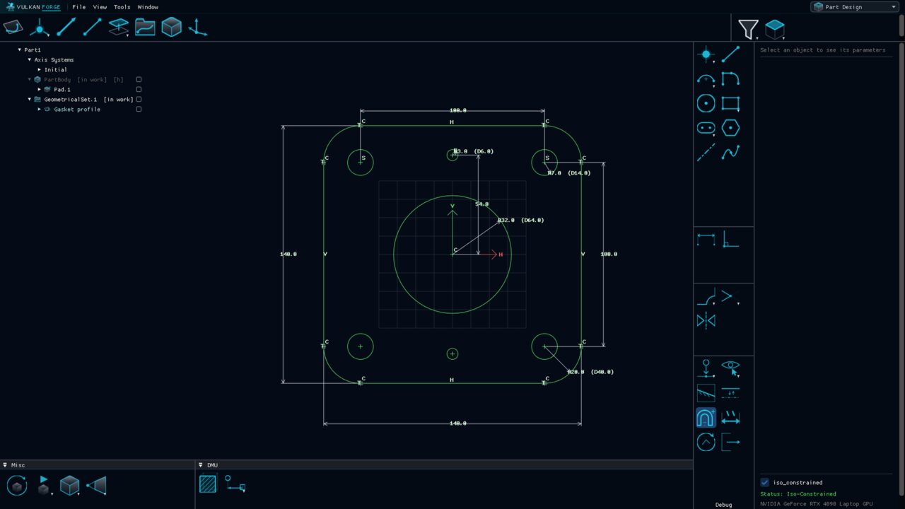
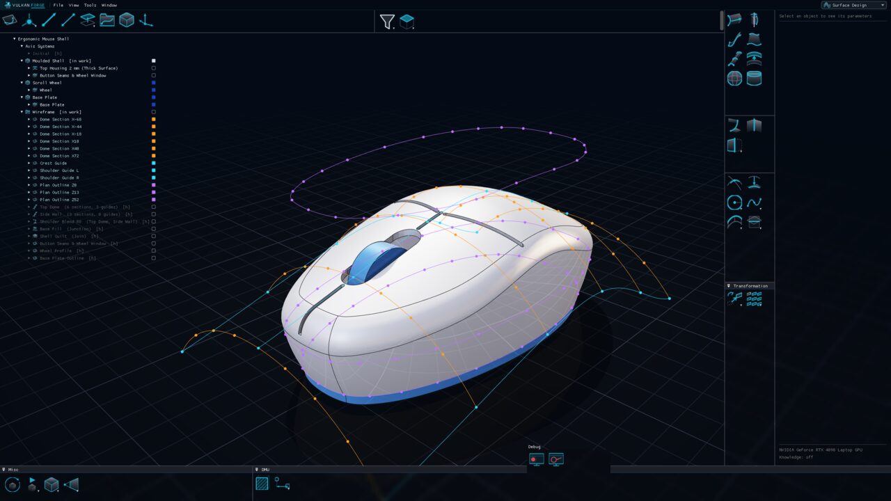
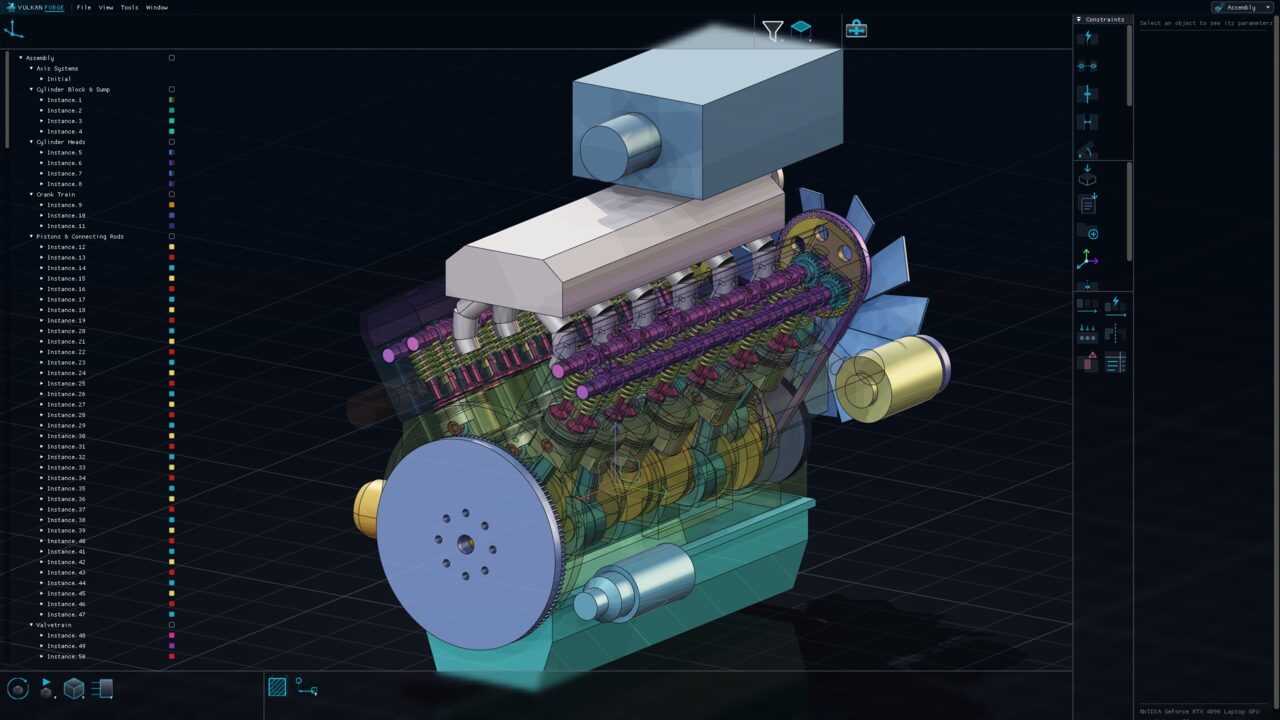
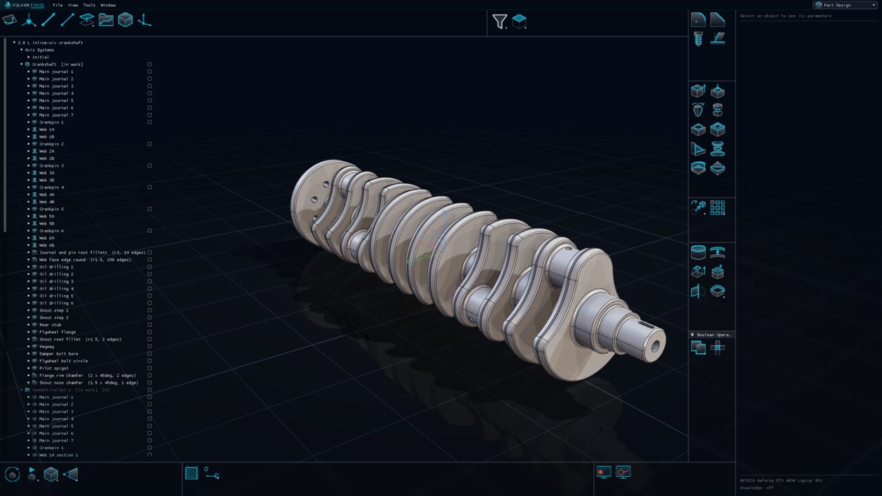
The 3.0 L inline-six crankshaft in the Part Design workbench: seven main journals, six crankpins and twelve tapered counterweight webs lofted like a forging, with root fillets, rounded web edges, oil drillings and a drilled flywheel flange, and every feature named in the specification tree.The Sketcher with a flange gasket profile: a rounded rectangle with tangent corner arcs, a central bore, four bolt holes and two dowels, every element green because the sketch is fully constrained, with linear, radius and diameter dimensions laid out around it.A computer-mouse shell in the Surface Design workbench: a smooth white housing lofted through orange cross-sections and cyan guide curves, with violet plan outlines, a blue scroll wheel and base plate, and the construction listed in the tree.The V12 engine in the Assembly workbench with the full application window: the spec tree grouped into Cylinder Block & Sump, Cylinder Heads, Crank Train, Pistons & Connecting Rods and Valvetrain, and the assembly toolboxes on the right.

Part Design

Solids with a history you can go back into

Pads, pockets, holes, dress-up features and patterns, each re-openable by double-click, in one history per body that you can reorder by dragging.

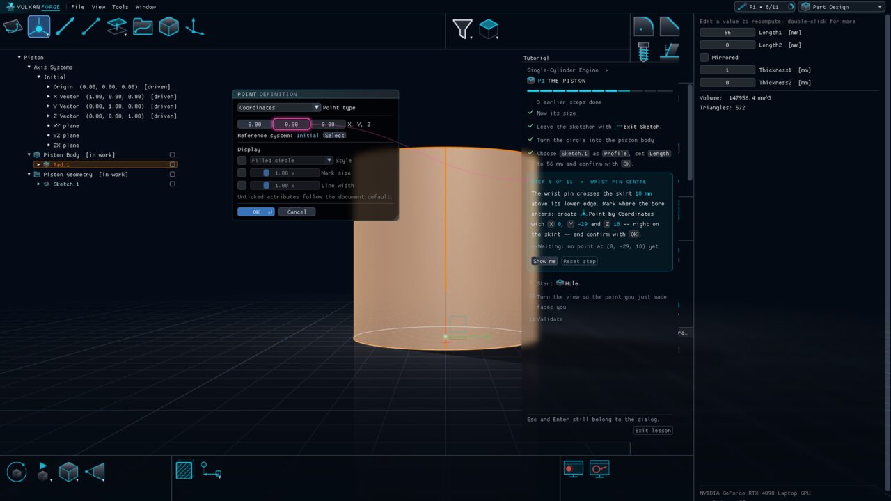
Tutorial lesson P1, the piston, in progress: the Tutorial panel shows the current step asking for a point by coordinates, and a pink guide ring highlights the exact Y field of the Point dialog it refers to.

Interactive tutorials

Learn VulkanForge inside VulkanForge: lessons open a prepared model, point at the exact control you need next, and move on by themselves when your model is right.

  • Open the Learn screen from the LEARN pill in the top bar or with F1: learning paths and a skill graph show what to learn next.
  • A lesson works in a sandbox — your own open documents are set aside and come back afterwards.
  • A guide ring points at the exact icon, dialog field, tree row or face, even through closed groups, other workbenches and folded tree nodes.
  • Steps complete automatically when the model reaches the right state; there is no Next button to click. Show me and Reset step are always there.
  • The final Validate step checks your part measurement by measurement, and Fix my mistakes repairs your own model as one undoable step.
  • Paths today: the interface, and a single-cylinder engine built part by part — piston, connecting rod, crankshaft and engine block.
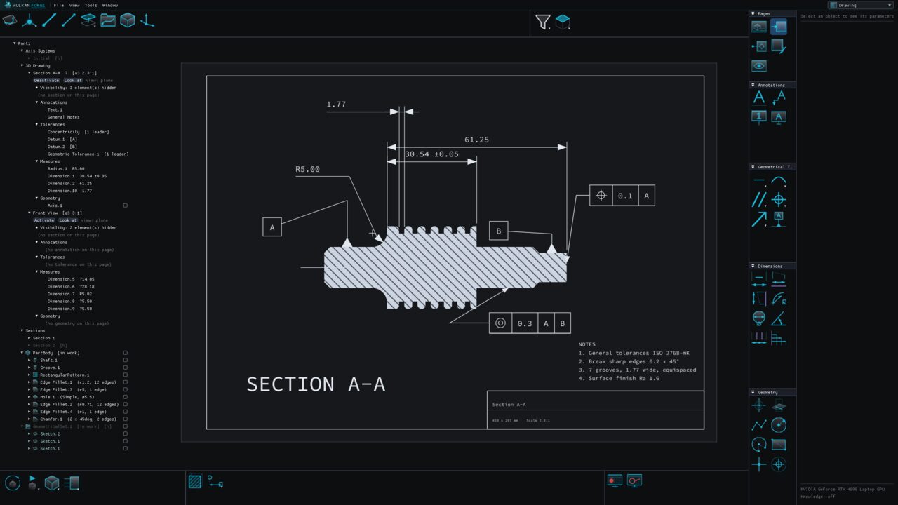
A drawing sheet in the Drawing workbench: SECTION A-A of a grooved stepped shaft with hatching, linear dimensions including a ±0.05 tolerance, a radius, datum features A and B, position and concentricity frames, a notes block and the title block, with the page tree on the left.

True-scale printing

Drawing pages print to PDF or SVG at the scale the page states.

  • Visible and hidden edges come from analytic hidden-line removal.
  • Each sheet carries an ISO 5457 frame and title block, and ISO 128 hatching drawn as line geometry.
  • Print one page or all pages into a single multi-page PDF, each sheet keeping its own format and scale.
  • Hidden pages are excluded, and each sheet is cut by its own section.
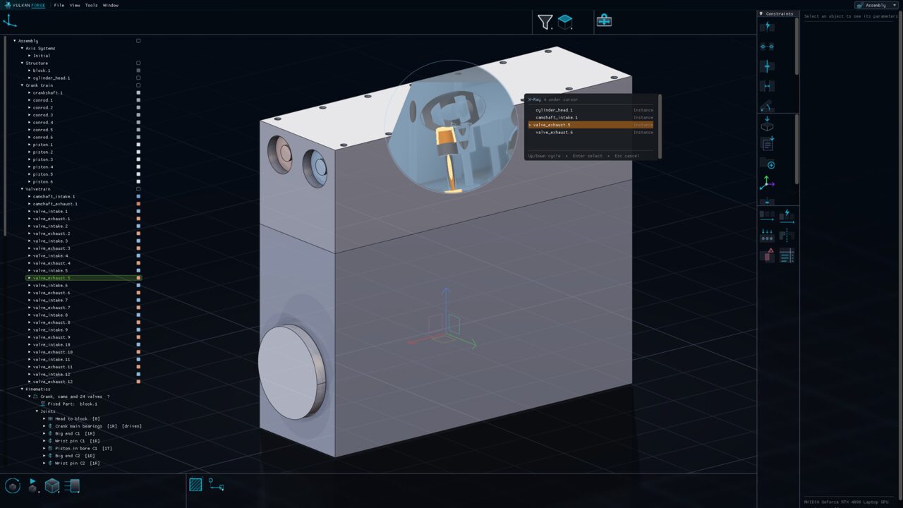
X-Ray mode on the inline-six: a see-through lens cut into the cylinder head shows an exhaust valve inside, and the depth-stack popup lists cylinder head, intake camshaft, exhaust valve and block under the cursor, with the exhaust valve focused.

X-Ray mode

List everything under the cursor in ray order and select what is behind something else.

  • Step through the stack with the arrow keys or the mouse wheel, nearest first.
  • A circular see-through window opens around the cursor as you go.
  • No camera move and no visibility change needed.
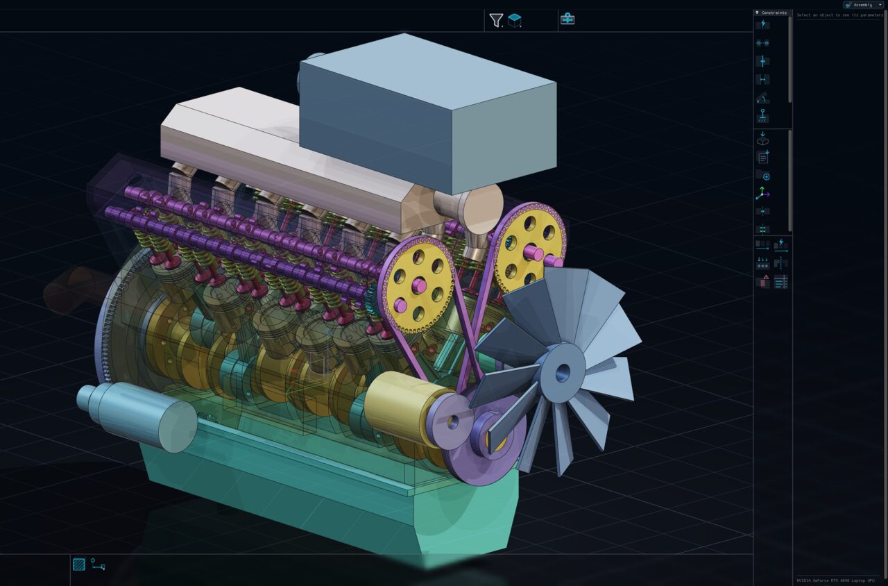
A complete V12 engine assembly in the ray-traced viewport: translucent block and heads reveal crankshaft, pistons, twin camshafts, valve springs and the timing belt driving both cam pulleys and the fan.

Physically based, ray-traced rendering

A realistic viewport with HDRI lighting, shadows and reflections that stays interactive on very large models.

  • Image-based lighting from an HDRI environment drives diffuse fill and reflections.
  • Ray-traced shadows and inter-part reflections on hardware ray-tracing GPUs, with shadow-map and planar-reflection fallbacks elsewhere.
  • A reflective ground plane with a real planar reflection of the part.
  • Identical bodies share one tessellation and one GPU copy; a 1094-body import of 12 unique parts needs 12 tessellations.

From part to drawing page

There is no drawing file. A drawing page lives inside the part, in the same specification tree as the shaft, the groove and the fillets, so it can never drift out of step with the geometry it documents.

recorded session · 1:1

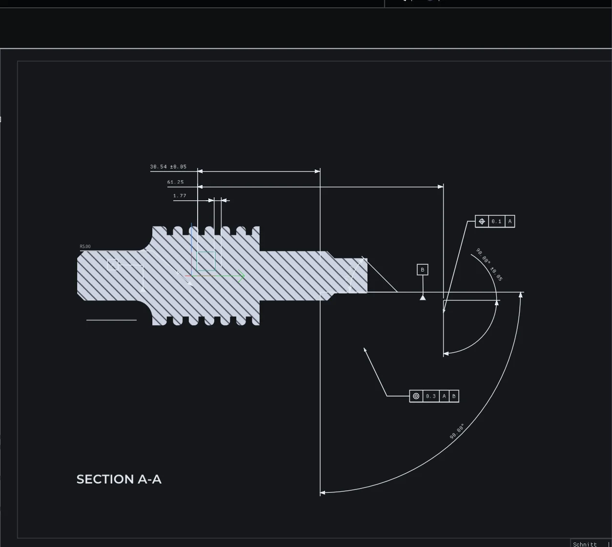
A recorded session, frame for frame. Activating a page is a camera move: the view eases round to the direction the page was defined from and locks to a parallel projection, because a drawing whose printed dimensions disagree with its own model is worse than no drawing. The sheet, the dimensions and the tolerance frames arrive with it — they were in the part the whole time. Activating the page switches the view to a parallel projection and squares it on. Nothing was extracted or exported: it is the same model and the same annotations, read as a sheet.

Activating a page switches the view to a parallel projection, because a drawing whose printed dimensions disagree with its own model is worse than no drawing at all. Dimensions follow ISO 129-1 and datums ISO 5459, and they reference the model rather than restating it.

And also

The rest of the toolkit

The knowledge system

A researched corpus of engineering design rules your LLM applies while it models — so the parts it builds follow the rules a good engineer would.

  • As a part is built, it is measured in the rules' own terms — wall thickness, hole depth-to-diameter, fillet radii, draft — and each rule is evaluated, blocking problems first.
  • Every rule that drove or checked a feature stays linked to that feature in the document: click a face and see which knowledge shaped it.
  • Experts can correct or add rules; every change is attributed and versioned.
  • Available with the Professional plan; Enterprise customers can host their own instance so their know-how never leaves the company.

Parameters and formulas

Every numeric value of a feature is a parameter that can be linked to a unit-checked formula over other parameters.

  • Lengths, angles, radii, counts and ratios are stored as typed parameters, not bare numbers.
  • Formulas use arithmetic with unit suffixes (mm, cm, m, in, deg, rad); a length parameter only accepts a length-valued result.
  • A formula-driven field is disabled in its dialog, just like a constraint-driven coordinate.
  • Sketch dimensional constraints and the part's own user parameters can be formula-driven too.

Exact geometry and minimal recompute

Curves and surfaces stay mathematically exact through the whole pipeline, and edits recompute only what depends on them.

  • A circle stays a true circle and an arc a true circular edge in profiles, faces, solids and exports; tessellation exists only for rendering.
  • Each body's history is built through a prefix cache: appending a feature applies only that feature, editing one re-applies only it and what follows.
  • Every shape-producing element has a content-signature cache, so upstream edits invalidate exactly the downstream results that consumed them.

Reference geometry

Points, lines, planes, vectors and axis systems with the full set of construction methods, available in every part workbench.

  • Points by coordinates, on curve, on plane, on surface, centre, tangent, between, extremum and polar extremum; multi-solution cases are numbered in the view.
  • Planes in ten construction types, including between two planes, mean through points and tangent to a surface.
  • Any feature that needs a direction accepts a vector, a line, a single-line sketch, a plane normal or an axis-system axis.

Sectioning

Cut the model with a plane to look inside it, without changing the part.

  • Non-destructive: turn the section off or delete it and the whole part returns unchanged.
  • Exposed cut faces of solids are hatched like a technical drawing.
  • Cut all bodies and surfaces or only selected ones; drag the plane in 3D and the view updates live.

Measure

Distances, angles, lengths, areas, volumes and mass properties, measured without changing anything.

  • Measure Between: minimum distance, angle where it applies, and X/Y/Z deltas between two elements.
  • Measure Item: an edge's length and radius, a face's area, a body's volume, a vertex's coordinates.
  • Measure Inertia: volume, area, mass, centre of gravity and principal moments of inertia.
  • Tick Keep measure to store it in the tree; a kept measure can be tracked by a kinematics Report.

STEP import and export

Exchange exact B-rep geometry with other CAD systems through STEP.

  • Import: one body per solid, loose geometry in a geometrical set, optional nested sets mirroring the file's assembly; unit conversion from mm, cm, m or inch.
  • Export: a named STEP assembly with one component per body and per geometrical set, element names kept, millimetres, no tessellation.
  • Export can include or leave out hidden geometry, and both directions run headless (MCP document.import_model / document.export_model).
  • Per-body STL and OBJ mesh export from a body's context menu.

3D Viewer export (HTML)

One self-contained HTML file with the model in 3D, every visible drawing page and a Print button.

  • Opens in any browser with no server, plug-in or network connection.
  • Selecting a page aims the 3D camera, applies that page's visibility and section, and shows its sheet.
  • The Print button produces a PDF byte-identical to the application's own printer.
  • Written by the backend, so it runs fully headless.

Video capture

Record the screen 1:1, or render the model headlessly into a clip.

  • Session recording (Ctrl+Shift+R) captures exactly what is on screen, for bug reports.
  • Document capture re-renders the model offscreen: turntable, camera path, feature playback or parameter sweep.
  • Mechanism playback renders a kinematics command sweep to video with no UI.
  • Formats: MP4 and WebM via an installed ffmpeg; MJPEG AVI, GIF and PNG sequence built in.

Dependency graph

A node graph of the document showing what feeds what, for parts and assemblies.

  • Every operation and element is a node; reference edges and sequence edges are drawn differently.
  • Drag an output pin onto an input to re-point it, or delete a link to disconnect it.
  • Available over MCP as document.dependency_graph, document.rewire_input and document.disconnect_input.

Cross-part references

Publish geometry from one part and import it into another as a live, exact link.

  • Bodies, surfaces, curves, splines, points, planes and axis systems can be published.
  • Imports follow the source when it changes; links are stored by file identity, so they survive a move or rename.
  • An imported solid can seed a body that later pads, pockets and holes machine.
  • Isolate freezes a standalone copy; Find missing files searches folders for broken links.

Report Defect

File a bug from inside the app with the misbehaving elements, marked-up screenshots and a frozen copy of the document.

  • Pick the misbehaving items in the tree or the 3D view.
  • Screenshots of the real window, marked up with crop, box, circle, arrow, pen and text.
  • Written as one container: a folder or a self-contained zip.

Open, readable file format

Documents are YAML files with a fixed header, so they diff, review and script like source code.

  • Two document types: vf_part for a single part and vf_asmbly for an assembly.
  • Every file starts with schema, type, file UUID and created/updated timestamps.
  • Files written over MCP are the same format the application opens.
Drive the kernel yourself

Not a recording. The sliders below build a part in the same exact geometry kernel the application runs, headless in a container, and every number that comes back is measured — not calculated in your browser.

vulkanforge kernel · headless

This browser has no WebGL2, so the model is not drawn. The measurements below still come from the kernel.

drag to rotate

document.measure

Volume
— mm³
Surface area
— mm²
Faces
—
Edges
—
Bounding box
—

Drive it with an LLM

VulkanForge ships a built-in MCP server — Model Context Protocol over HTTP — that talks to the backend rather than to the UI. A built-in MCP server lets any MCP-capable LLM — or any script — build, check, render and save real models: parts, assemblies, mechanisms and generative studies. Everything works without a window, too.

127.0.0.1:8765/mcp

  1. sketch.create{plane:"XY"}→ S1
  2. sketch.add_entity{sketch:S1, type:"rectangle", x:0,y:0,w:20,h:14}→ ok
  3. geometry.validate{target:S1}→ {valid:true, closed:true}
  4. feature.pad{sketch:S1, length:10}→ Pad.1
  5. document.measure{}→ {volume:2800, bbox:…}
  6. document.save{path:"block.vf_part.yaml"}→ ok

geometry.validate before a pad and document.measure after it are how the model checks its own work — no rendering, and no human in the loop to describe the result back to it. Run headless it writes a file; run inside the open application the geometry lands in the live document and you watch it appear.

Headless or live

Run it with no window and no GPU and it writes a file you open later. Run it inside the open application and the geometry appears in the live document, frame by frame.

It can check its own work

geometry.validate says whether a profile actually closes; document.measure returns volume, area and bounding box. A failed call comes back as an error the model can correct.

Off by default, local only

The server starts only when you ask for it, and listens on 127.0.0.1 alone. Model changes run on the single owner thread, so editing from a model and from the UI never conflict.