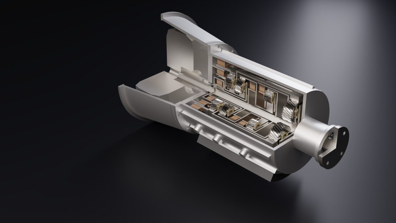
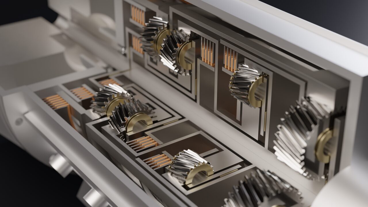
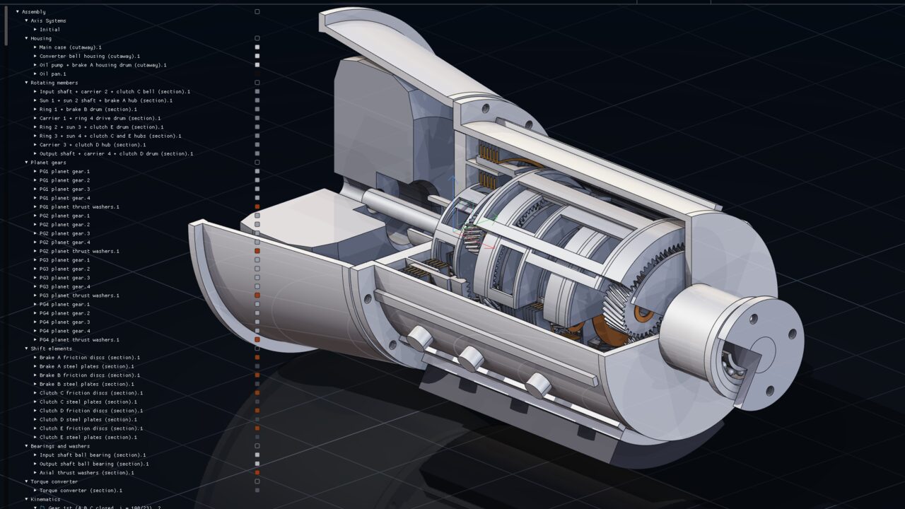
VulkanForge is parametric CAD with exact geometry, photoreal rendering and a built-in MCP server, so the LLM of your choice can build real machines. The 8-speed automatic on this page — 34 parts, 10 mechanisms, 649 joints — was built that way, then shifted through its gears as a mechanism.
Your LLM builds the machine. VulkanForge keeps it exact.
A built-in MCP server lets any MCP-capable LLM — or any script — build, check, render and save real models: parts, assemblies, mechanisms and generative studies. Everything works without a window, too.
Bring your own LLM: any client that speaks MCP over HTTP can drive VulkanForge — the machines on this site were built that way.
The LLM sees what it builds: view.render returns images of the model, and measurements and topology queries return exact numbers to check against.
The backend owns the model; the UI is an optional thin client, so a headless run produces the same files and shapes as the app.
MCP server over JSON-RPC 2.0 on 127.0.0.1 with self-describing tools — run standalone (vulkanforge_mcp) or inside the app, where edits appear live.
geometry.validate before a pad and document.measure after it are how the model checks its own work — no rendering, and no human in the loop to describe the result back to it. Run headless it writes a file; run inside the open application the geometry lands in the live document and you watch it appear.
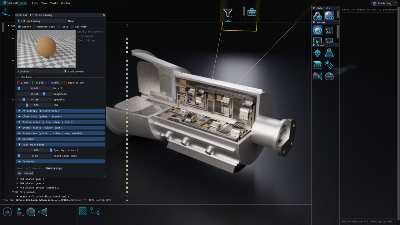
A cutaway 8-speed automatic transmission with four helical planetary sets and five shift elements, every tooth an exact involute. It reproduces all nine published gear ratios and runs a 3rd-to-4th shift as a mechanism.
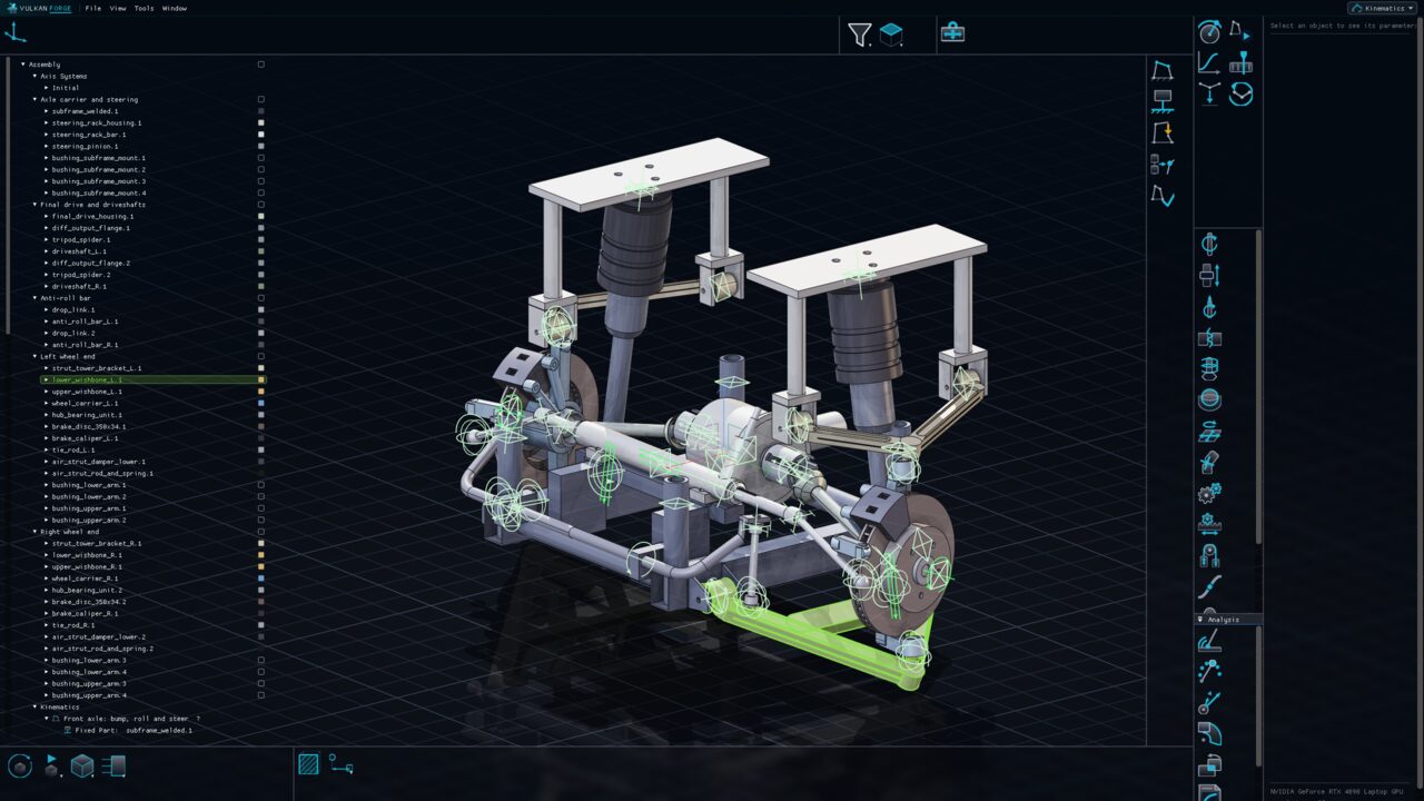
8-speed planetary automatic, cutaway — path tracedHelical planetary sets and clutch packsMid-shift in the Kinematics workbench
New in VulkanForge
Learn it inside the app. Show it off photoreal.
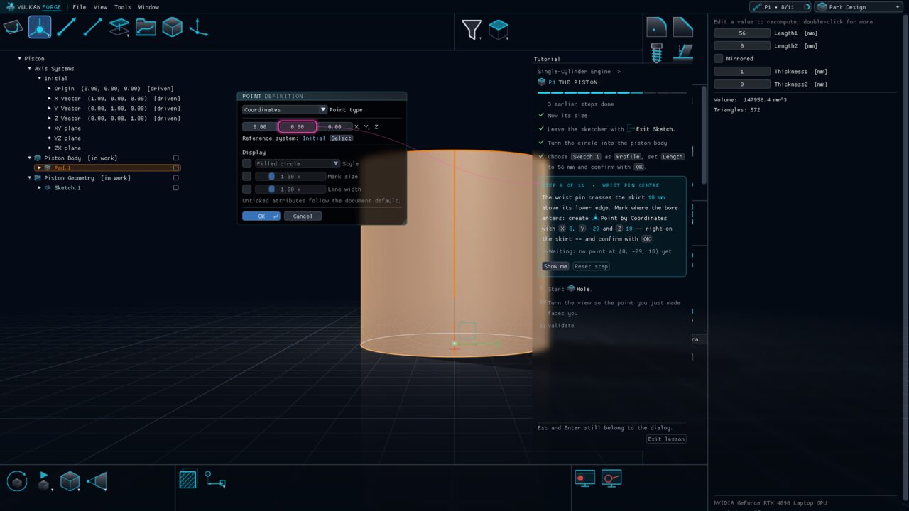
Interactive tutorials
A tutor that points at the right button
Learn VulkanForge inside VulkanForge: lessons open a prepared model, point at the exact control you need next, and move on by themselves when your model is right.
A guide ring points at the exact icon, dialog field, tree row or face, even through closed groups, other workbenches and folded tree nodes.
Steps complete automatically when the model reaches the right state; there is no Next button to click. Show me and Reset step are always there.
The final Validate step checks your part measurement by measurement, and Fix my mistakes repairs your own model as one undoable step.
Photoreal stills and videos, straight from the model
A physically based GPU path tracer turns a part or an assembly into a photoreal image or a video of its mechanism. Materials, lights, cameras and the environment are saved in the document, so any render can be repeated later, by anyone, with the same result.
Forty measured materials. Cast iron, machined and brushed steel, bead-blasted and anodized aluminium, chrome, brass, car paint, glass, rubber, carbon fibre and more — or your own, with clear coat, anisotropy, transmission, sheen, subsurface and procedural textures.
Materials follow the colour rules. A material is assigned like a colour — per body, per feature or per set — and stays with the part when it is placed in an assembly. Round edges makes sharp CAD edges catch a highlight without touching the geometry.
Real units, real cameras. Point, spot, area and sun lights in lumens and lux with colour temperatures in kelvin; cameras with focal length, depth of field and exposure; a physical sky placed by location, date and time.
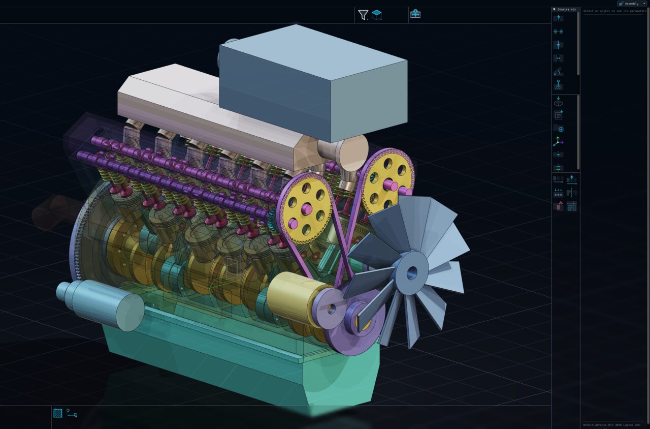
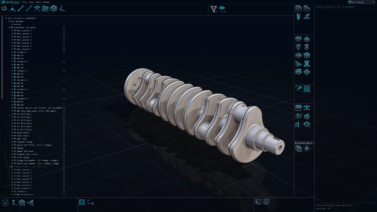
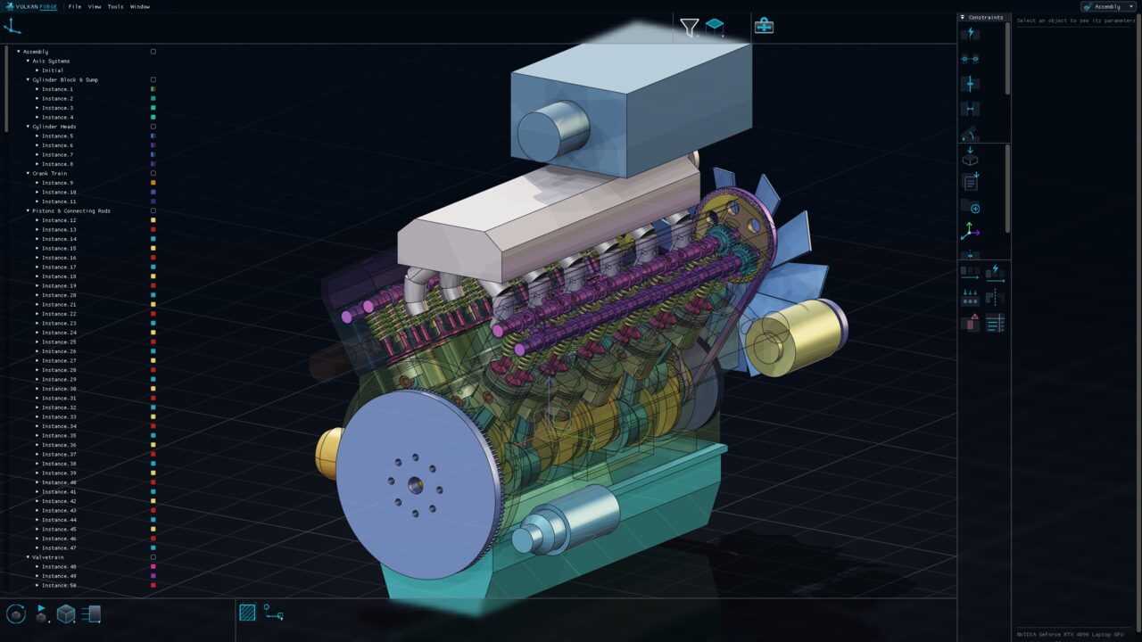
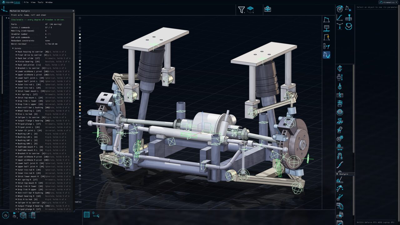
A transmission, an engine and a suspension — modelled, assembled, jointed and measured in VulkanForge. Open one to see what is in it and how it was made.
From the first sketch to the drawing, the stress plot, the mechanism and the final render. Dialogs, pickers and the manipulator behave the same way in every one of them.
Part Design
Feature-based solids with one reorderable, parametric history
Build solid bodies from sketches and surfaces with pads, pockets, holes, sweeps, lofts, dress-up features, booleans and patterns. Every feature lives in a single per-body history you can reorder by dragging, and every dimension is a parameter you can drive from a formula.
Constraint-driven 2D profiles that never silently break
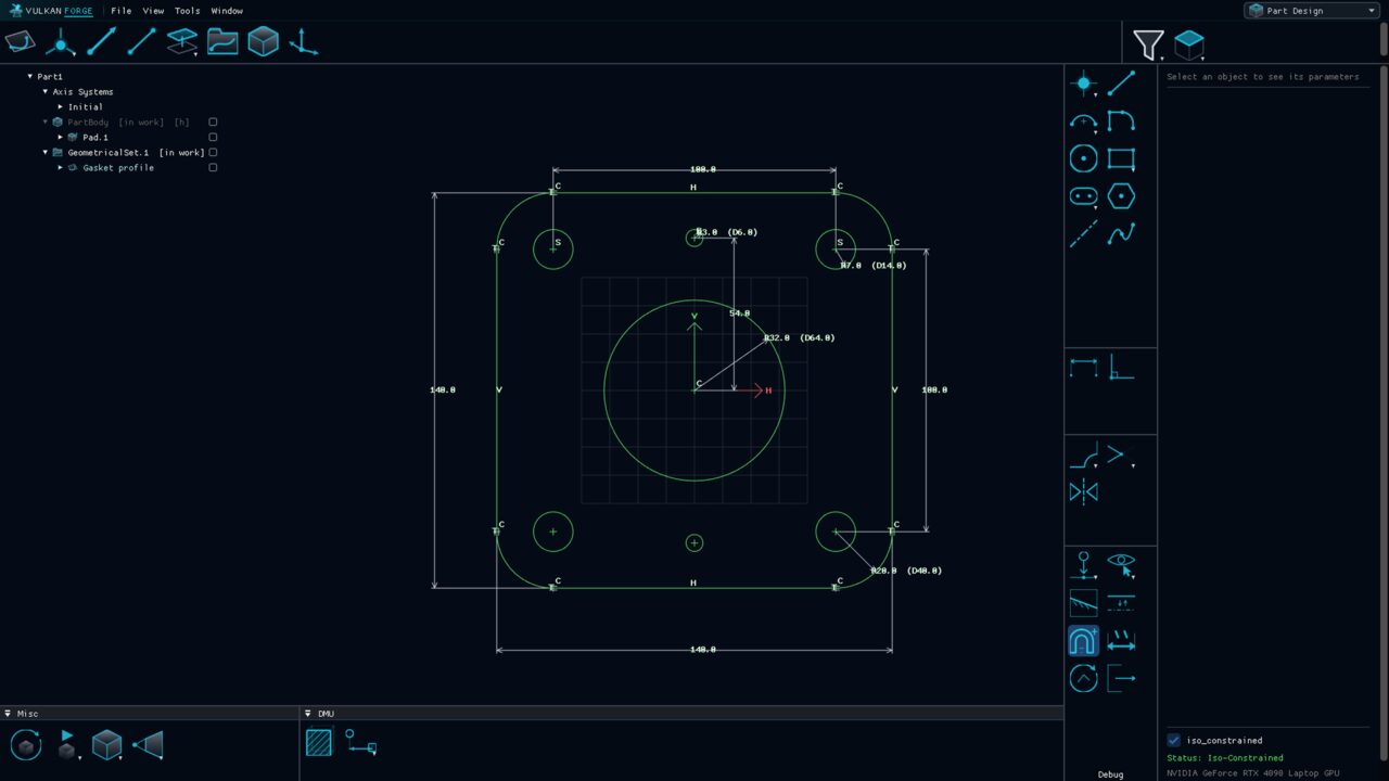
The 2D environment where profiles are drawn and solved. Geometry is exact lines, circular arcs and splines built from points, driven by geometric and dimensional constraints, and coloured by how constrained it is.
Exact wireframe and surfaces for shapes solids cannot reach
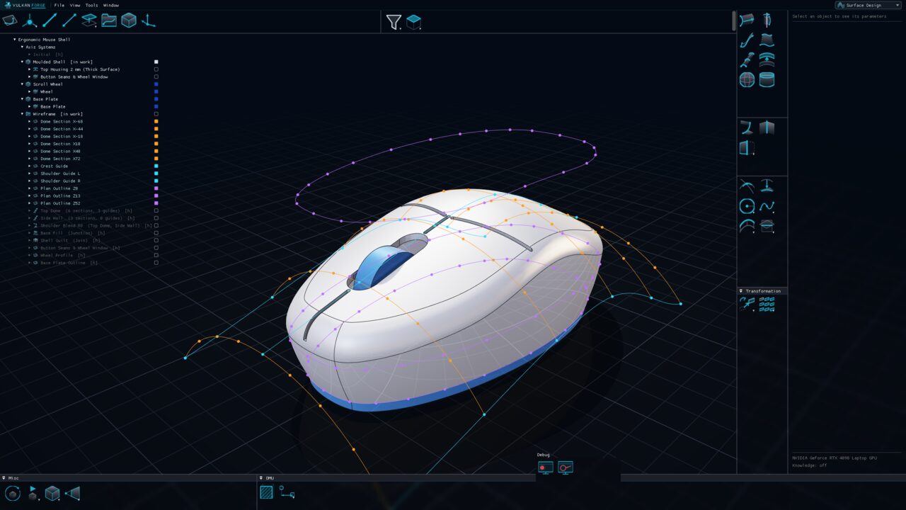
Build class-A-style shapes from exact 3D curves and surfaces: extrudes, revolves, sweeps, fills and multi-section lofts, reworked with split, trim, join, healing and rolling-ball fillets. Curves and surfaces stay mathematically exact; nothing is baked into a tessellated approximation.
Live part instances, persistent constraints, clash and BOM
Place parts as live instances inside nestable groups — edit the part and every instance follows. Position them by manipulation, snapping or persistent constraints, replicate them, and check the product with exact clash analysis and a bill of material.
Joints, commands and simulation — with analytic, checkable numbers
Turn an assembly into a mechanism: connect instances with joints, ground one part, drive the remaining freedoms with commands or laws of time, and simulate. Mobility, speeds and accelerations come from the constraint Jacobian, and reports, sweeps and clash-in-motion turn the motion into numbers.
Printable 3D drawing pages that live inside the part
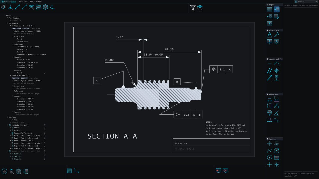
Turn a part into 3D pages: saved, true-scale views with their own sheet format, visibility and sections, annotated with notes, dimensions, datums and geometrical tolerances. Pages live inside the part and reference the model, so they cannot drift out of step with it.
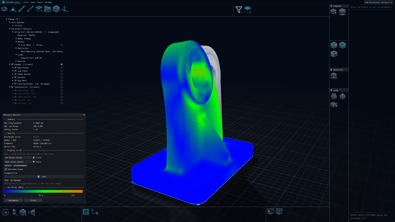
Compute how a part deforms and where it is stressed under load, directly on its solid bodies — no separate analysis document to keep in step. Cases, meshes, materials, restraints and loads live in the part; results go to a regenerable sidecar that is flagged out of date when the model changes.
Generative design: declare the constraints, generate the part
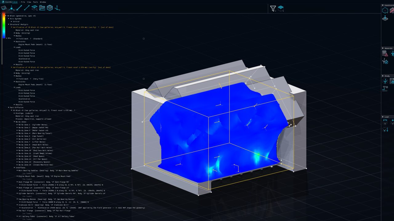
Instead of modelling a part, describe what it must satisfy — the envelope it may occupy, the zones it must avoid, the interfaces it must carry and their loads, the material and the print process — and generate the connective material. Interfaces stay exact geometry; the result can be verified with an independent finite-element solve.
Photoreal stills and videos, straight from the model
A physically based GPU path tracer turns a part or an assembly into a photoreal image or a video of its mechanism. Materials, lights, cameras and the environment are saved in the document, so any render can be repeated later, by anyone, with the same result.
In most CAD the drawing is a second document, the analysis a third and the mechanism a fourth, and keeping them in step is your job. Here they are parts of the same object.
Every workbench for 30 days with a free account — no card, nothing held back. After that, pick the plan that fits: every plan includes every workbench.