Workbenches
Every workbench, and what is in it
There is no module to buy: every plan includes every workbench on this page.
Part workbenches
Everything that makes one part: solids, sketches, surfaces, its drawing pages, its analysis and its generative studies all live in the same part document.

Part Design
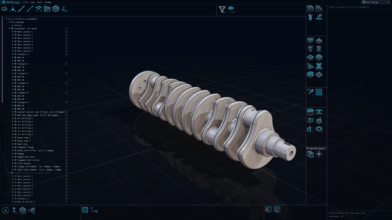
Feature-based solids with one reorderable, parametric history
Build solid bodies from sketches and surfaces with pads, pockets, holes, sweeps, lofts, dress-up features, booleans and patterns. Every feature lives in a single per-body history you can reorder by dragging, and every dimension is a parameter you can drive from a formula.
Explore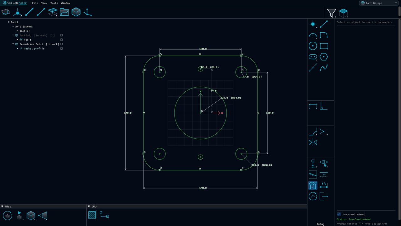

Sketcher
Constraint-driven 2D profiles that never silently break
The 2D environment where profiles are drawn and solved. Geometry is exact lines, circular arcs and splines built from points, driven by geometric and dimensional constraints, and coloured by how constrained it is.
Explore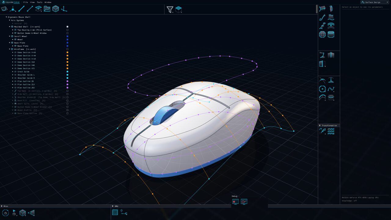

Surface Design
Exact wireframe and surfaces for shapes solids cannot reach
Build class-A-style shapes from exact 3D curves and surfaces: extrudes, revolves, sweeps, fills and multi-section lofts, reworked with split, trim, join, healing and rolling-ball fillets. Curves and surfaces stay mathematically exact; nothing is baked into a tessellated approximation.
Explore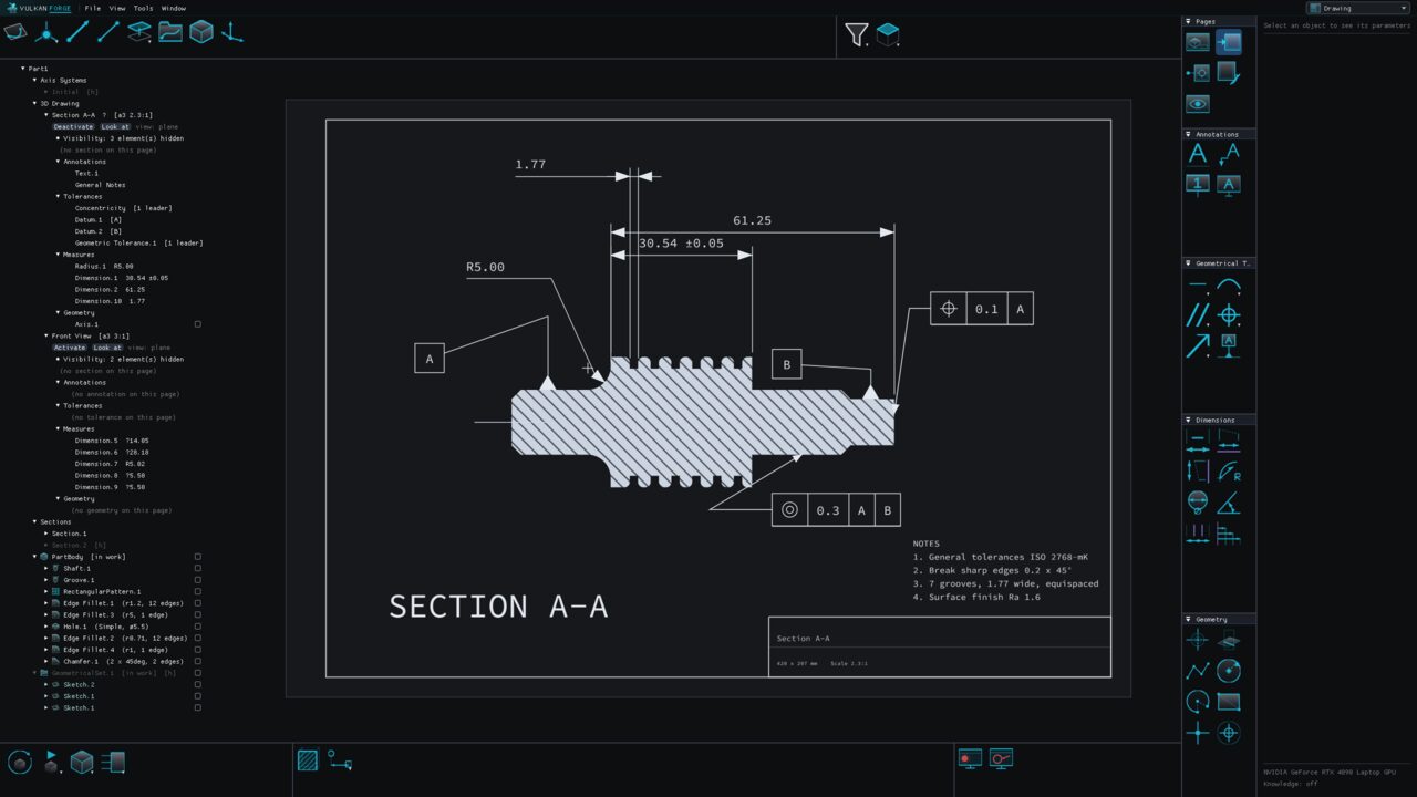

Drawing
Printable 3D drawing pages that live inside the part
Turn a part into 3D pages: saved, true-scale views with their own sheet format, visibility and sections, annotated with notes, dimensions, datums and geometrical tolerances. Pages live inside the part and reference the model, so they cannot drift out of step with it.
Explore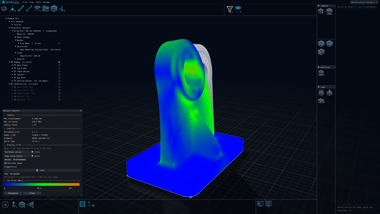

Structural Analysis
Linear-static FEA on the part you are designing
Compute how a part deforms and where it is stressed under load, directly on its solid bodies — no separate analysis document to keep in step. Cases, meshes, materials, restraints and loads live in the part; results go to a regenerable sidecar that is flagged out of date when the model changes.
Explore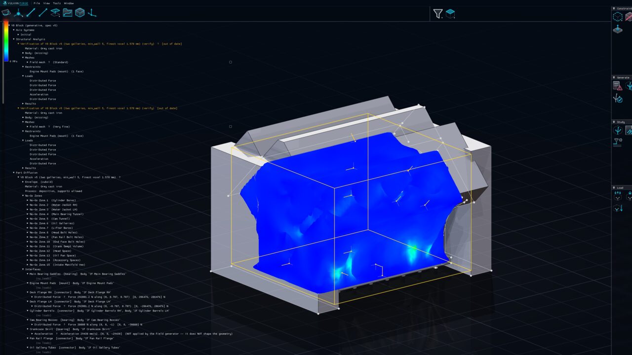

Part Diffusion
Generative design: declare the constraints, generate the part
Instead of modelling a part, describe what it must satisfy — the envelope it may occupy, the zones it must avoid, the interfaces it must carry and their loads, the material and the print process — and generate the connective material. Interfaces stay exact geometry; the result can be verified with an independent finite-element solve.
ExploreAssembly workbenches
Assemblies place live part instances and hold the mechanism: constraints, joints, commands and simulation live in the same assembly document.

Assembly
Live part instances, persistent constraints, clash and BOM
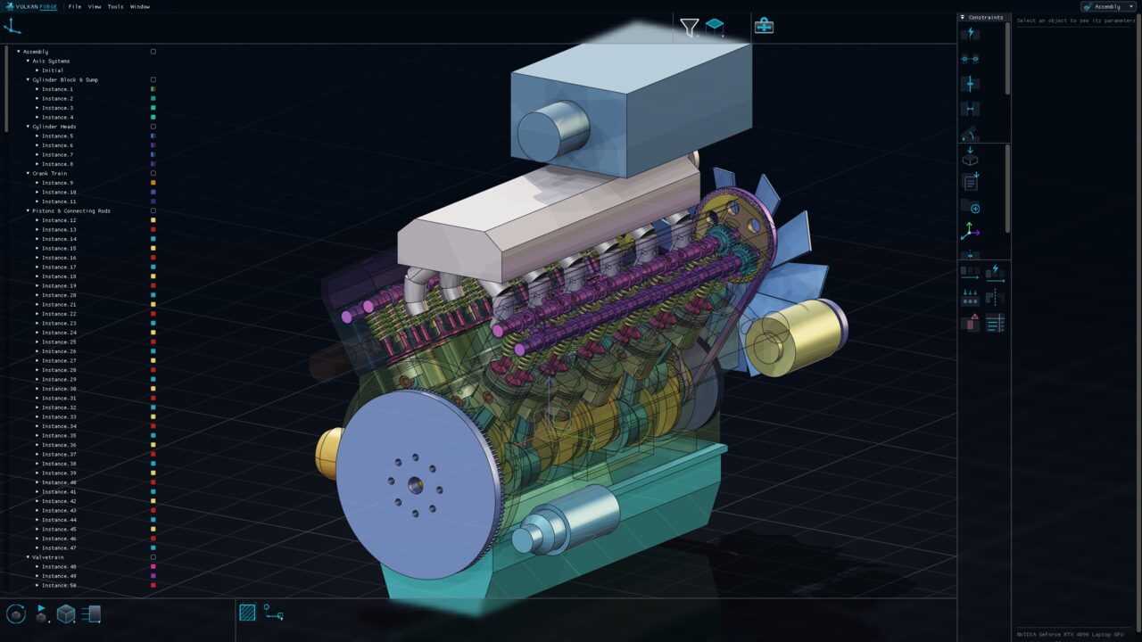
Place parts as live instances inside nestable groups — edit the part and every instance follows. Position them by manipulation, snapping or persistent constraints, replicate them, and check the product with exact clash analysis and a bill of material.
Explore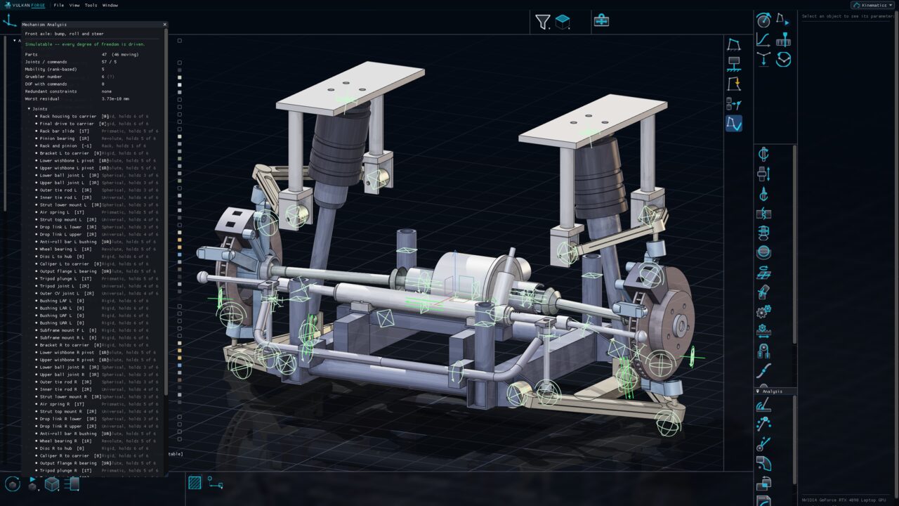

Kinematics
Joints, commands and simulation — with analytic, checkable numbers
Turn an assembly into a mechanism: connect instances with joints, ground one part, drive the remaining freedoms with commands or laws of time, and simulate. Mobility, speeds and accelerations come from the constraint Jacobian, and reports, sweeps and clash-in-motion turn the motion into numbers.
ExploreFor parts and assemblies
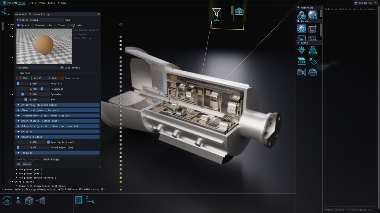
Rendering works on any document: materials, lights and cameras are saved with the part or assembly they belong to.