Light, simulated
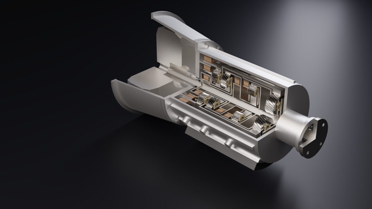
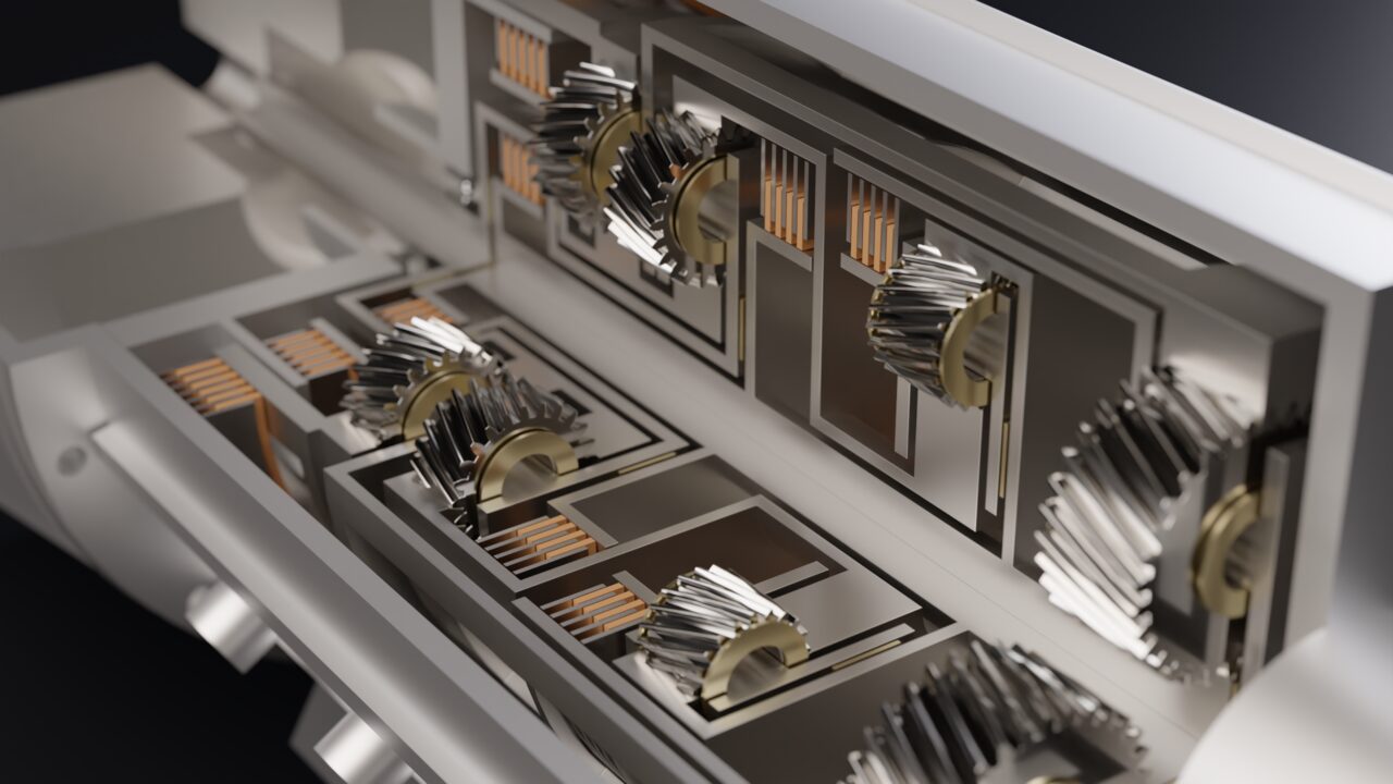
Light bounces between surfaces, through glass and under the skin of plastics, so reflections, soft shadows and colour bleeding come out the way a camera would record them. The result is denoised.

Rendering
A physically based GPU path tracer turns a part or an assembly into a photoreal image or a video of its mechanism. Materials, lights, cameras and the environment are saved in the document, so any render can be repeated later, by anyone, with the same result.
Why it matters
Light bounces between surfaces, through glass and under the skin of plastics, so reflections, soft shadows and colour bleeding come out the way a camera would record them. The result is denoised.
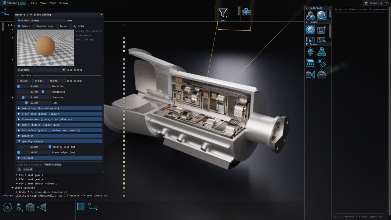
Cast iron, machined and brushed steel, bead-blasted and anodized aluminium, chrome, brass, car paint, glass, rubber, carbon fibre and more — or your own, with clear coat, anisotropy, transmission, sheen, subsurface and procedural textures.
A material is assigned like a colour — per body, per feature or per set — and stays with the part when it is placed in an assembly. Round edges makes sharp CAD edges catch a highlight without touching the geometry.
Point, spot, area and sun lights in lumens and lux with colour temperatures in kelvin; cameras with focal length, depth of field and exposure; a physical sky placed by location, date and time.
Render a kinematics simulation of an assembly as MP4, WebM, AVI or GIF — every frame path traced, every pose re-solved.
Every step — materials, lights, cameras, environment, stills and videos — is available to your LLM or script through the MCP server, and falls back to the CPU on machines without ray-tracing hardware.
Operations
The complete inventory, toolbox by toolbox, with the icons exactly as they appear in the application.
 Point LightOmni-directional light in lumens, with a radius for soft shadows
 Spot LightA cone of light with an adjustable angle and soft edge
 Area LightRectangular or round soft box — the most realistic studio light
 Sun LightParallel light in lux, with an angular size for soft shadows
 CameraSave the current view with focal length, depth of field and exposure
 EnvironmentStudio, industrial, urban, outdoor or night HDRI, a physical sky, or a colour
 Material LibraryBrowse about forty built-in materials and apply one to the selection
 New MaterialCreate a material in the editor, with a live path-traced preview
 Live PreviewReplace the viewport with the path-traced image, refining as you watch
 Render ImageRender a final still at the output size (PNG or EXR)
 Render VideoRender a kinematics simulation of an assembly as a video
 Render SettingsOutput size, samples, bounces, denoising, tone mapping and ground
In use